Using Silverlight's Path
A collection of linked lines, curves, and other basic graphics elements is called a graphics route. This article shows how to utilize XAML and C# to provide Path control in Silverlight.

Introduction
A graphics path is a set of connected lines, curves, and other simple graphics objects, including rectangles, ellipses, and text. A path works as a single graphics object, so an effect applied to the graphics path will be applied to all the components of the path. For example, if a graphics path contains a line, a rectangle, and an ellipse and we draw the path using a red stroke, all three components (line, rectangle, and ellipse) of the graphics path will be drawn with the red stroke.
The Path object represents a path shape and draws a path. The Path object draws both closed and open paths. A closed path is a shape that has the same start and endpoints and an open path is a shape that has different start and endpoints.
The Fill property fills the interior of an ellipse. The Stroke property sets the color and StrokeThickness represents the width of the outer line of an ellipse.
The Data property of the Path object defines a shape or a collection of shapes in form of Geometry.
The Path element represents a Silverlight Path control in XAML
<Path/>
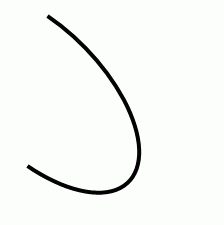
The code snippet in Listing 1 creates a Path and draws an arc by settings its Data property.
<Path Stroke="Black" StrokeThickness="4"
Data="M 80,200 A 100,50 45 1 0 100,50" />
The output looks like
The Path Syntaxes
Let us take a look at the Data attribute of the Path code used in the previous section.
<Path Stroke="Black" StrokeThickness="4"
Data="M 80,200 A 100,50 45 1 0 100,50" />
As you may see from the above code snippet, the Data attribute has the letter M followed by two comma-separated numbers, letter A is followed by two comma-separated numbers, and letter O is also followed by two comma-separated numbers.
- The letter M represents a move action and moves to the given point from the current point. For example, M 80,200 command moves from the current point to the point (80, 200).
- The letter L draws a line from the current point to the specified point. For example, the L 100,200 command draws a line from the current point to the point (100, 200).
- The letter H draws a horizontal line from the current point to the specified point towards the x-axis.
- The letter V draws a vertical line from the current point to the specified point towards the y-axis.
- The letter C draws a cubic Bezier curve from the current point to the third point and two points in between are used as the control points.
- The letter S draws a smooth cubic Bezier curve from the current point to the second point and the first point is used as the control point.
- The letter Q draws a quadratic Bezier curve from the first point to the second point and the first point is used as the control point.
- The letter T draws a smooth quadratic Bezier curve from the first point to the second point and the first point is used as the control point.
- The letter A draws an elliptical arc. It takes five parameters - Size, IsLargeArc, Rotation Angle, Sweep Direction, and Endpoint.
- The letter Z closes the current path by drawing a line from the current point to the starting point.
Using Geometries within a Path
The LineGeometry class represents the geometry of a line. The StartPoint and EndPoint properties of the LineGeometry class define the start and endpoints of a line. The following code snippet creates the geometry of a line.
<LineGeometry StartPoint="20,50" EndPoint="200,50" />
The RectangleGeometry class represents the geometry of a rectangle. The Rect property of the RectangleGeometry defines the starting points, width, and height of a rectangle. The following code snippet creates the geometry of a rectangle.
<RectangleGeometry Rect="80,167 150 30"/>
The EllipseGeometry class represents the geometry of an ellipse. The Center property of the EllipseGeometry defines the center of an ellipse. The RadiusX and RadiusY define the width and height of an ellipse. The following code snippet creates the geometry of an ellipse.
<EllipseGeometry Center="80,150" RadiusX="50" RadiusY="50" />
The GeometryGroup creates a composite geometry that is a combination of multiple Geometry objects.
The code listed in Listing 2 creates a GeometryGroup with three geometry shapes - a line, an ellipse, and a rectangle and sets the Data property of a path.
<Path Stroke="Black" StrokeThickness="3" Fill="Blue" >
<Path.Data>
<GeometryGroup >
<LineGeometry StartPoint="20,200" EndPoint="300,200" />
<EllipseGeometry Center="80,150" RadiusX="50" RadiusY="50" />
<RectangleGeometry Rect="80,167 150 30"/>
</GeometryGroup>
</Path.Data>
</Path>
The output of Listing 2 looks like
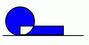
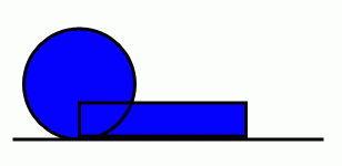
The FillRule property of the GeometryGroup class specifies how the intersecting areas of geometry objects in a GeometryGroup are combined. It has two values – EvenOdd and NonZero. The default value of the FillRule is EvenOdd. In this case, the intersecting area of two shapes is not filled. In the case of NonZero, the interesting area of two shapes is filled. By setting the FillRule to NonZero generates Figure 3.
Create a Path Dynamically
The code listed in Listing 3 creates Figure 2 dynamically. As you can see from Listing 3, we create a LineGeometry, an EllipseGeometry, and a RectangleGeometry and then we create a GroupGeometry and add all three geometries to the GroupGeometry. After that, we simply set the Data property of Path to the GroupGeometry.
/// <summary>
/// Creates a blue path with black stroke
/// </summary>
public void CreateAPath() {
// Create a blue and a black Brush
SolidColorBrush blueBrush = new SolidColorBrush();
blueBrush.Color = Colors.Blue;
SolidColorBrush blackBrush = new SolidColorBrush();
blackBrush.Color = Colors.Black;
// Create a Path with black brush and blue fill
Path bluePath = new Path();
bluePath.Stroke = blackBrush;
bluePath.StrokeThickness = 3;
bluePath.Fill = blueBrush;
// Create a line geometry
LineGeometry blackLineGeometry = new LineGeometry();
blackLineGeometry.StartPoint = new Point(20, 200);
blackLineGeometry.EndPoint = new Point(300, 200);
// Create an ellipse geometry
EllipseGeometry blackEllipseGeometry = new EllipseGeometry();
blackEllipseGeometry.Center = new Point(80, 150);
blackEllipseGeometry.RadiusX = 50;
blackEllipseGeometry.RadiusY = 50;
// Create a rectangle geometry
RectangleGeometry blackRectGeometry = new RectangleGeometry();
Rect rct = new Rect();
rct.X = 80;
rct.Y = 167;
rct.Width = 150;
rct.Height = 30;
blackRectGeometry.Rect = rct;
// Add all the geometries to a GeometryGroup.
GeometryGroup blueGeometryGroup = new GeometryGroup();
blueGeometryGroup.Children.Add(blackLineGeometry);
blueGeometryGroup.Children.Add(blackEllipseGeometry);
blueGeometryGroup.Children.Add(blackRectGeometry);
// Set Path.Data
bluePath.Data = blueGeometryGroup;
LayoutRoot.Children.Add(bluePath);
}
If we need to generate a single geometry, we do not need to use a GeometryGroup. We can simply set geometry as the Data of the Path. The following code snippet sets an EllipseGeometry as the Data property of a Path.
<Path Stroke="Black" StrokeThickness="3" Fill="Blue" >
<Path.Data>
<EllipseGeometry Center="80,150" RadiusX="50" RadiusY="50" />
</Path.Data>
</Path>
Formatting a Path
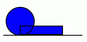
We can use the Fill property of the Path to draw a Path with any kind of brush including a solid brush, linear gradient brush, radial-gradient brush, or an image brush. The code in Listing 4 uses linear gradient brushes to draw the background and foreground of a Path.
<Path Stroke="Black" StrokeThickness="3">
<Path.Data>
<GeometryGroup>
<LineGeometry StartPoint="20,200" EndPoint="300,200" />
<EllipseGeometry Center="80,150" RadiusX="50" RadiusY="50" />
<RectangleGeometry Rect="80,167 150 30" />
</GeometryGroup>
</Path.Data>
<Path.Fill>
<LinearGradientBrush StartPoint="0,0" EndPoint="1,1">
<GradientStop Color="Blue" Offset="0.25" />
<GradientStop Color="Orange" Offset="0.50" />
<GradientStop Color="Green" Offset="0.65" />
<GradientStop Color="Red" Offset="0.80" />
</LinearGradientBrush>
</Path.Fill>
</Path>
The new Path looks like Figure 4.
Setting Image as Background of a Path
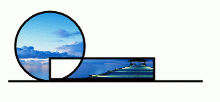
To set an image as the background of a Path, we can set an image brush as the Fill of the Path. The code in Listing 5 sets fills the Path with an image.
<Path.Fill >
<ImageBrush ImageSource="dock.jpg" />
</Path.Fill >
The new output looks like Figure 5.
Drawing a Semi-transparent Path
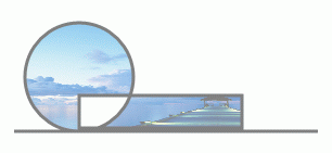
The Opacity property represents the transparency of a Path. The value of Opacity is between 0 and 1, where 0 is fully transparent and 1 is fully opaque. The code listed in Listing 6 generates a semi-transparent shape.
<Path Stroke="Black" StrokeThickness="3" Opacity="0.5" />
The new output looks like Figure 5.
Summary
In this article, I discussed how we can create a Path control in Silverlight at design-time using XAML and at run-time using C#. We also saw how we can format a Path by setting its fill property. After that, we saw you set an image as the background of a Path. In the end, we saw how to draw a semi-transparent Path.
HostForLIFE.eu Silverlight 5 Hosting
HostForLIFE.eu is European Windows Hosting Provider which focuses on Windows Platform only. We deliver on-demand hosting solutions including Shared hosting, Reseller Hosting, Cloud Hosting, Dedicated Servers, and IT as a Service for companies of all sizes. We have customers from around the globe, spread across every continent. We serve the hosting needs of the business and professional, government and nonprofit, entertainment and personal use market segments.
